Currie Enterprises Anti-Rock Off-Road Sway Bar
By Chad
Crowell
Intro | Installation | On-Road | Off-Road |
Conclusions
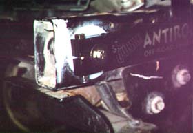
ABOUT THE KIT
The Anti-Rock was packaged in a think round cardboard
tube, and all parts arrived in perfect shape. The kit comes
with:
-
1- 35
¾ Sway Bar- SAE 4130 Heat-treated steel
-
2- 18
End Arms- Allow firmness adjustment of
kit
-
2- 9
End Links- Fully adjustable for different lift heights with heim
jointed ends
-
2
- 3
Plastic Bushings- Installed in ends of front crossmember to
support sway bar
-
Hardware- All necessary hardware to install
the kit is included
-
Instructions- Well thought out and easy to
follow
Its plain to see the kit is
well made. Upon assembly, all the parts fit together snugly
and easily. Everything lined up just perfect.
 INSTALLATION INSTALLATION
Installation took about an hour by myself. Youll
only need basic hand tools, block(s) of wood and heavy mallet or
a long adjustable clamp.
Remove front bumper and
winch (if equipped).
Remove stock swaybar
and end links/disconnects from frame and axle.
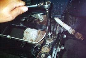
Using a file, de-burr
the inside holes of the front crossmember.
This is the round-ish tube
at the very front of your frame.
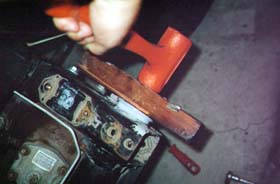
Using the mallet and
wood blocks, or the long clamp and wood blocks, install the plastic
inserts into the holes in the ends of the front crossmember.
They will only fit in one
way, and it is pretty obvious.
Be sure to use the wood blocks to spread the force of the
hammer/clamp so you do mot deform the plastic
inserts.
 Lightly grease the ends
of the sway bar and the insides of the plastic inserts.
Push the sway bar
through one end of the crossmember, and out the other end.
It may take a few mallet
blows or use of the clamp to force it through.
Center the sway bar in the
crossmember.
Loosely install the
3/8-24x 2 ½ bolts and 3/8 nylock nuts through the small hole on
the end of the 18 end arms.
Place the end arms on
the ends of the sway bar.
The end arms should slide on easily and be flush with the end
of the sway bar sticking through the center of them.
Be sure the end arms
are parallel on each side of the Jeep.
Install the 5/16 flat
washers, 5/16 lock washer, and 5/16-24x ¾ bolts into the holes in
the ends of the sway bar.
Snug them down securely. Lightly grease the ends
of the sway bar and the insides of the plastic inserts.
Push the sway bar
through one end of the crossmember, and out the other end.
It may take a few mallet
blows or use of the clamp to force it through.
Center the sway bar in the
crossmember.
Loosely install the
3/8-24x 2 ½ bolts and 3/8 nylock nuts through the small hole on
the end of the 18 end arms.
Place the end arms on
the ends of the sway bar.
The end arms should slide on easily and be flush with the end
of the sway bar sticking through the center of them.
Be sure the end arms
are parallel on each side of the Jeep.
Install the 5/16 flat
washers, 5/16 lock washer, and 5/16-24x ¾ bolts into the holes in
the ends of the sway bar.
Snug them down securely.
 Tighten the clamping
bolts and nuts, securing the end arms to the sway
bar.
Rotate the assembly so
that the end arms are parallel to the frame.
Measure the distance
between center adjustment hole in the end arms and the axle end sway
bar mounts. This is the
length to make the provided end links.
You may need to cut some of
the threaded rod off to shorten the links.
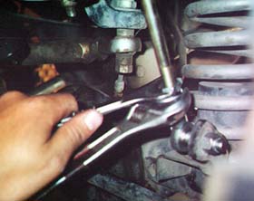
Once the correct length
is set on the end links, install them onto the swaybar and axle
brackets with the provided hardware.
Be sure to tighten the
jam nuts on the end links so the threaded rod does not rotate
between the heim joints.
Reinstall bumper and
winch (if equipped).
Double check all
hardware for tightness. Tighten the clamping
bolts and nuts, securing the end arms to the sway
bar.
Rotate the assembly so
that the end arms are parallel to the frame.
Measure the distance
between center adjustment hole in the end arms and the axle end sway
bar mounts. This is the
length to make the provided end links.
You may need to cut some of
the threaded rod off to shorten the links.
Once the correct length
is set on the end links, install them onto the swaybar and axle
brackets with the provided hardware.
Be sure to tighten the
jam nuts on the end links so the threaded rod does not rotate
between the heim joints.
Reinstall bumper and
winch (if equipped).
Double check all
hardware for tightness.
 The installation is pretty much a no brainer. It takes a bit
of muscle to hammer the Nylon inserts on, but overall, you should
run into no real problems. The installation is pretty much a no brainer. It takes a bit
of muscle to hammer the Nylon inserts on, but overall, you should
run into no real problems.
Before driving, check your
turning circle for rubbing. After I installed the Anti-Rock,
my tires rubbed on the end links in sharp turns, requiring me to
add washers to the steering stops on the knuckles.
NEXT>>
Intro | Installation | On-Road | Off-Road |
Conclusions
|