|
|
|||||||||||||||||||||||||||||||||||||||||||||||||||||||||||||||||||||||||||||||||||
| Tools, Prep and Concerns I point this out because I truly believe this is an installation where you can buy the products directly from JB and in a weekend of time in your garage you can save yourself some money by "doing it yourself." This installation was done entirely in my two car garage using basic hand tools and a small set of air tools powered by the Craftsman compressor my wife and daughter bought me a few years ago for Father's Day. In anticipation of doing this project yourself, I can tell that you will need only a few things that you may not have:
Installation:
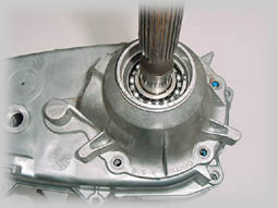
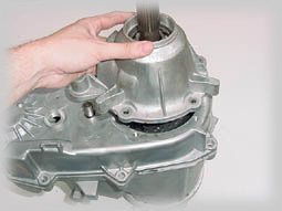
The first thing I did was place a jack stand under the back of the 231 and place a jack under the transfer case skid plate. Then I unbolted the six bolts that hold the plate to the bottom of the frame. I then removed the four nuts that hold the skid plate to the transmission/transfer case mount (this is a great opportunity to check your transmission mount. As usual, mine was busted, so I replaced it. For more info on changing a tranny mount, check out this article on How to Replace the TJ Transmission Mount). After removing the two bolts that tie my engine skid plate to the t-case skid plate I lowered the jack and took the transfer case plate out from under the jeep. With the t-case plate removed, I placed the jack at a good balance point on the transfer case and jacked it up until it was lifted off the jack stand. I shortened the jack stand and moved it to a suitable position forward of the transfer case. I used the transmission mount. I then lowered the t-case back down until it was sitting firmly on the jack stand, but I didn't remove the jack - I left it in place to provide support for the transfer case. Then I drained the fluid out of the transfer case. The next step was to remove the two electrical connections to the transfer case. The first is at the backside and it is the speedometer connection (note this for later). The second is on the drivers side and goes to the 4 wheel drive indicator on the dash board. I then removed the six 14 mm nuts that face the transmission. This is pretty easily accomplished, except for the two upper nuts on the passenger side. Depending on the size of your forearms you may find some difficulty getting a good stroke with your wrench because of the muffler. Be patient and they will all come out. After all the nuts were removed, I pulled the shift lever brackets off the studs and tucked the bracketry up and out of the way so it didn't catch on anything as I lowered the transfer case. Slowly rock the transfer case back and forth, watching the studs to see how far it is moving apart from the transmission. There may be some fluid loss between the transmission and transfer case when the seal separates, but it is normal and nothing to worry about. Once I cleared the studs, I balanced the transfer case on the jack with my hand and had a helper lower it to the ground and then simply slid the jack out from under the vehicle. Obviously, having a friend help you at this point makes the job a lot easier, but it can be done by one person. The Teardown:
Since I already had a SYE installed on my transfer case, I could immediately get started, but for those of you following along at home who have a stock 231, you will need to remove the dust shield and the rear output seal. Both of these are detailed in the JB Instructions and shouldn't be too much of an issue. Then remove the main shaft retaining ring and the spacer which is underneath the ring. Set them aside because you will not need them again. I then unbolted the rear bearing housing by removing the five bolts holding the housing to the back half of the case. Once the bolts are removed you may need a soft hammer or something to help jar the housing loose. I would be cautious of trying to pry it up since it is an aluminum case.
Now the transfer case pump is exposed. This pump is what lubricates the transfer case. The pump should stay on top of the rear case half as the rear case half is lifted off of the front half because the pump is connected to a pickup tube and a screen inside the rear case housing pulling the pump up can crack the tube or the pump itself . This is actually a common occurrence and can be avoided by taking a couple of seconds to be careful with it. I removed the bolts holding the two case halves together. I had to find the two slotted areas on the case - there is one in the upper left hand corner and one in the lower right hand corner - where I had to place a screwdriver and pry the two case halves apart. Again, take your time here, as it took me a good while just to find the slots because on my case they were filled with RTV and road grime. The case may be stubborn, but it will come apart.
Once I had the case halves separated I removed the spring from the top of the mode fork. The JB Instructions now tell you to lift the main shaft assembly out of the case, but what they don't tell you is that you have to remove the front yoke from the front side output shaft before you can lift the assembly out. I'm sure this is a simple oversight, but it could cause some minor frustration in the field (JB assures me this oversight will be fixed in the next pass of their instructions).
In order to remove the front yoke you will either need a impact wrench and socket or you will need to set the unit on the floor or have someone hold it and use a breaker bar. This nut will most likely be extremely difficult to remove because it is torqued 130 ft. lbs.
Once you have the front yoke removed, the assembly will be easy to remove, although I simply lifted mine up just enough to remove the chain and set the shafts back down. This provided a good place to hold them while I worked on the next few steps. I did remove it completely to lube the shift rod and internal components for the final assembly. Using a pair of flat snap ring pliers I removed the large retaining ring on the top of the main shaft. This allowed me to slide the hub and the sprocket assemblies off of the shaft. This is well-documented in the JB instructions and I won't duplicate that here. In our case we did not reuse the sprocket because we received a new one with the Wide Chain Kit.
I put the sprocket and the hub on the new JB Conversions 32 spline shaft and installed the new retaining ring that came with the kit.
I installed the main shaft and the shift fork back into the front half of the transfer case then looped the chain (in my case the new wide chain) around the sprocket that is part of the front output shaft (or the new front output shaft in my case) and the main sprocket. I then lowered the front output shaft into the front bearing cavity. This required a little patience to get it lined up - especially with the new chain, but it finally slid into place.
I replaced the large spring that I had removed from the top of the mode fork. That was it for the internal portion and it was time to put the case back together. At this point, I inspected the pump and the pump screen for problems (perhaps this should have been done right after I got the case apart). In my case, we found an issue that needed to be corrected. The screen was plugged with debris and silicone from a previous repair. I can only assume that it was installed incorrectly, with too much silicone when the original Currie Kit was installed in 1997.
I replaced the screen and purchased a new o-ring for the seal between the pump and the pickup tube. It's probably a good idea to inspect and perhaps replace these pieces anyway since they are relatively low cost and you already have the case open. It seems like good insurance to me.
Once you have the back half of the case put together it should look like this. The pump sits on the outside and the tube connects to it on the bottom. Also, I made sure to clean off the magnet and place it back in its slot in the case. Then I applied a nice bead of RTV around the entire surface of the case, putting some water on my finger kept the silicone from sticking to me (this is a good trick to know if you choose to use your finger to smooth the bead around the entire surface).
I gently installed the back half of the case onto the front half. I did encounter a little trouble getting the splines on the pump to line up with the splines on the shafts. It was somewhat tricky, but with a little patience it slipped right into place. You may also need to tap the area around where the shift rod protrudes through the back half of the case in order to get the case half to seat all the way down. I installed a couple of bolts at opposite corners and then spun the output shaft to make sure everything spun freely and nothing was binding. I then re-installed the front output yoke, without torquing it down just yet, but snugged it up good and tight.
I put the rest of the bolts in the case half and tightened them down. Be sure to remember to replace the cable hold-downs on the proper bolts so that you can route the wiring back to the same points it was connected to before.
Once again, I checked to make sure that everything was spinning freely. Other than a slight drag, the shafts should spin and not be "locked" in place.
Now that I had the two halves put back together, I slid the tone ring down onto the main shaft. Be sure to place the tone ring correctly, with the indented side facing out. It will not work properly if it is installed backward.
I prepared the new rear bearing housing by applying a thin layer of grease to the lip of the new seal and, in my case, I also applied a thin layer of silicon to the edges of the housing. Be careful not to block or load up a lot of silicon in the area that extends over the shift rod. I slid the new rear bearing housing over the main shaft and bolted it into place. I made sure that the bolts were torqued down to 30 ft. lbs.
Now that I had the case back together it was time to put the yoke on. This part became tricky. In fact, I made a mistake here that forced me to have to pull my rear driveshaft later on (but I will get to that momentarily). First, I installed the rubber star washer, then applied a layer of silicon to the nut and the threads. This will keep any fluid that seeps through on the spline at bay. I start the nut by hand and then drive it down with an impact socket. The instructions tell you to toque it to 180 ft lbs. but I don't think many "home" mechanics have that setting on their torque wrench. A trick here may be to reinstall the transfer case in the vehicle and then torque the yoke nut down (on both the front and rear output shafts).
Once the yoke was in place, I installed the new speedometer sensor into the housing. It should fit easily and not bind. It has a plastic clip that allow it to connect to the OEM wire loom bolted to the top of the case.
Once again I checked to make sure that everything was spinning freely. Other than a slight drag the shafts should spin and not be "locked" in place. After the final check, I reinstalled the transfer case back into my Jeep, filled it with the proper fluid (in the case of the NP 231 it uses Chrysler ATF), installed the front shafts and plugged the electrical connection back together. You will notice that the new electronic speed controller plugs nicely into the factory harness on the back of the transfer case. If you have your rear driveshaft go ahead and install it at this time, as well.
In my case, because of the height of my Jeep, the age of my rear driveline and the design of the older Currie Kit that used a flange instead of a yoke, I opted to order a new rear shaft from JB Conversions. In order to get it measured properly, I waited until the transfer case was installed back in the Jeep so I could take an exact measurement, which was 21-1/2" between the yokes (rear output shaft yoke to the input yoke on my Dana 44). That makes it almost 3" longer then the shaft I had on there with the Currie Kit. My shaft was a little over 16" long, plus the 3" of the flange (which doesn't help with the angle at all), so having a true ~22" long resting shaft should drop my angles and increases the life of my u-joints. An extra bonus was that removing the shaft from the Currie system required removing 4 bolts from the flange with very little room to work. The new yoke only requires removing the 4 bolts that directly hold the u-joint on, which is a much simpler solution. |
|||||||||||||||||||||||||||||||||||||||||||||||||||||||||||||||||||||||||||||||||||


|
Help spread the ROCKCRAWLER world!
Share on Facebook
|