|
|
|||||||||||||||||||||||||||||||||||||||||||||||||||||||||||||||||||||||||||||||||||||||||||||
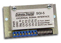
| Dakota Digital Universal Electronic Speedometer Interface (SGI 5A):
Evidently, my Pro-Comp 35's are entirely too short and as I found out, my 36" TSL Radials are a smidge too tall to be exactly accurate without the Dakota Digital device. As many of you know, the rating on the sidewall is really a guesstimate of the tire size once it's mounted on a rim and rolling on the pavement (or dirt, or rock or whatever). Most people could live with a speedometer that is either 3 mph to slow or too fast, but being the person I am, I wanted it to read right dead on. So I opted for the Dakota Digital SGI-5. Neither Dakota Digital nor JB offer any detailed instructions for installing this in a Jeep. However, the installation is fairly simple and should be accomplished in less than an hour (unless, of course, you are like me and always manage to find some issue to fix - many times having nothing to do with the project I am doing). Using the Dakota Digital instructions (use application #2) and a little common sense, this installation is quite simple, as the hookups to the device are pretty straight forward.
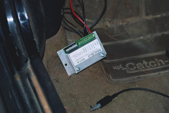
First, I decided on a location that would be easily accessible, but up out of the weather and out of the grime. The unit is not sealed and you really wouldn't want it to be submersed or covered in grease and dirt for long periods of time. I decided to mount it inside the cab (at the suggestion of Dakota Digital's Tech Support) and the best place I found was the kick panel on the driver's side of the interior. I mounted it there behind my roll cage and it is out of the way, but very accessible if I need to change the switch settings for any reason (like swapping to my off-road tires or perhaps completely changing tire sizes in the future). Then, I looked in my service manual to determine what wire I needed to splice into for the speedometer signal. I thought about trying to find the wire going directly to the speedometer behind the dash but scrubbed that idea when I realized that there were 400 wires packed into the loom going to the back of the unit and it would be a nightmare to un-tape and sort out. So on to plan two, which turned out to be quite easy. The wire coming from the factory speed sensor at the transfer case was orange and white. I traced that wire to determine which wire that connected to on the JB Conversions speedometer harness (it's the yellow on my harness) and I decide to splice into that wire.
I ran two wires from the drivers side floor board, thru an existing firewall grommet, across the engine side of the firewall to the wire center in the middle and then followed the wiring loom down to the transfer case. At that point, I removed the JB Conversions harness and cut the yellow wire. I attached one of the new wires to the side coming from the transfer case and the other to the side coming from the ECM. In layman's terms, I connected one wire to each side of the wire I just cut.
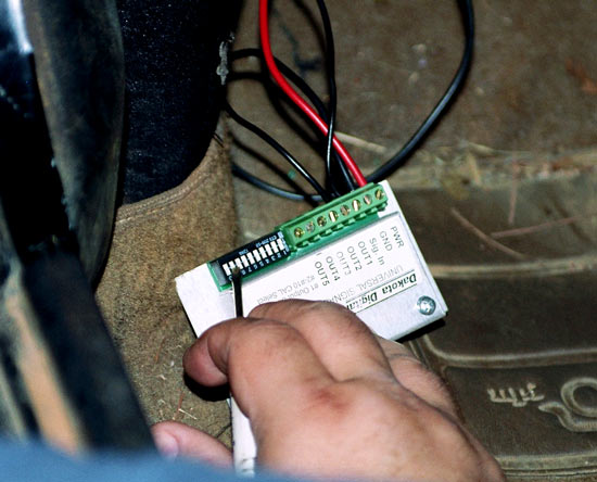
In order to show you how simple this installation is, I chose not to solder the wires, and instead, used crimp-less connectors (Posi-Lock) that can be purchased at most auto parts or hardware stores. The only tools I needed were a wire stripper and a cutter. I used black wire, but I would recommend using two different color wires so that you can keep them straight when you climb back out from underneath. Going back up to the to the driver's floorboard, I took the wire coming from the transfer case sensor and attached it to the SGI-5 where it says "Sig In" and attached the other wire (the one going to the ECM) to where it says OUT2 (OUT1 and OUT2 are commonly used for this type of calibration. I actually saw no major difference in using OUT1 or OUT2 but ultimately used OUT2 because it was the recommendation made by Dakota Digital tech support). Next, I found a ground wire (or you can run one to ground the Dakota Device and connected it in a clean fashion, as you will need to make sure you have a good ground). I was fortunate that I have a ground screw already installed for my CB and off-road lights so I installed a crimp-style connector with a hole to pass a bolt thru and screwed it into the same location as the ground for my CB and lights. I connected a power wire to the back of the cigarette lighter which will provided me with easy access to a "switched" power source (meaning it turns off and on with the key and is not live all the time). Then I installed those wires into the appropriate slots on the SGI-5 (power goes to PWR and the ground wire goes to GND).
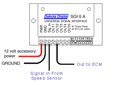
Here a quick redraw of the diagram that shows you exactly what wire to hook up. Remember that "Sig. In" is the side coming from the transfer case and that OUT2 runs to the Speedometer (or ECM).
According to the SGI-5 instructions the dip switches should be set to the following before the first test drive. This sets the SGI-5 unit to a 1:1 pass thru so that you have a known place to begin your adjustments.:
Once you have the switches set I recommend a short test drive before you tidy everything up (be sure your new wires are not laying across the exhaust system or near something that might cut them and make sure the unit and wires do not interfere with your driving). Take the vehicle around the block and make sure the speedometer is reading approximately where it was reading before you made any changes. If anything seems different, relax, take a deep breath and review each of these steps again. Make sure you have the correct wires going to the correct connectors on the SGI-5.
If everything seems copasetic then go ahead and tidy things up. I used wire ties to secure the two new wires I ran to the factory wiring loom all the way through the engine compartment and right on down back to the t-case. Another caution I was given by the guys at Dakota Digital is to be careful about binding the wiring to tight to each other as this can cause chaffing of the wire and the signal could bleed across from one wire to the other providing an erratic reading - basically causing the speedometer to appear to jump or drop slightly at speed. If you want to clean things up even more, you cansolder the wire into place and heat shrink them for years of service (this is something I intend to do in the future). In the interior, I placed the Dakota Device in the position I already had selected. You may need to drill two holes to mount it. I choose to mount mine using Velcro so I could remove it easily to make changes or move it to another location if this one didn't work out. Once I had placed the SGI-5 unit into position, I used wire ties to get the excess wiring out of the way so I don't catch it on a foot or anything that might be sharing its space and bolted my dash and everything back together for the last time.
Now you will need a friend with another car or a Radar Gun or perhaps a GPS unit. Go drive the vehicle in a safe place and manner up to an actual speed of 60 mph. How will you know when you have reached 60? Well you will either need to have a friend with a radio or a cell phone driving around you to let you know, perhaps you have access to a radar gun (or can coerce a friendly neighborhood officer to help you out) or do what I did and mount my GPS and find an open section of roadway. At 60 MPH on my GPS the speedometer in my Jeep shows approx 63 miles per hour. Using the formula offered in the SGI Instructions I get a number of .952 (actual speed / speedometer reading or 60/63). Using this number I see that the switches 2 thru 10, which are used for the calibration adjustment, must be changed. Now at 60 MPH my speedometer is pretty much dead on.
Once I put my off-road tires on I zeroed the Dakota Digital out again by turning switches 8 and 9 back on and driving it. I discovered that with these tires, which are much taller then the Pro-Comps, I read 60 MPH on the Speedo but am actually running ~62 MPH (yeah big whoop but same can be applied to much larger tires , as well). Using the Dakota Digital formula of 62/60 (actual speed/ speedometer reading) I got a reading of 1.03. Then I looked at the chart and knew that I need to change the switches to match this chart. Now my speedometer reads correctly for my off-road tires, as well.
Final Impressions: The installation was really easy and simple and really just requires some time and patience to make sure all the parts are installed correctly - including making sure that everything it torqued to the proper specs. The Dakota Digital device also works well and is easy to install. The hardest part is finding the location and running the two or three wires you will need to make the hook-ups. However, the hook-ups can be completed with common auto parts crimp-less or crimp type connectors and should provide years of fault free service. The support from both JB Conversions and Dakota Digital where outstanding and both had answers for me when I called without having to call me back or put me on hold for any length of time (and I will point out that if the instructions are followed, one may never evenneed to call them). I am satisfied with this kit and believe that for the for the money (approx $100 more than a regular Heavy Duty SYE Kit) it is the only way to go. It will allow me to make many changes over the next few years without having to worry about vibrations or angles and with the 32 spline output shaft and wider chain and sprocket(s) I won't have to worry about breaking it, either. The entire solution from JB gives me the confidence that my 231 is beefy enough to run bigger tires, agile enough to maintain the proper u-joint angles and that my speedometer is accurate enough to avoid tickets. It also means that my whole setup is adjustable should I decide to move up to 38" tires or swap my lift for something else or decide to change my axles or gears.
|
|||||||||||||||||||||||||||||||||||||||||||||||||||||||||||||||||||||||||||||||||||||||||||||
 Yeah,
it's along name for a fairly simple product. Basically, it
recalibrates the signal coming from the speed sensor to adjust
for changes in gearing and/or tire size. In the
case of the JB Conversions kit, JB set their electronic sensor
and tone ring to emulate the tallest factory tire and gear package
available from Jeep, which is 4.10 gears and roughly 31" tires. This should work
fairly well with a true 35" diameter tire and 4.56"
axle gears, but may be off by a few MPH.
Yeah,
it's along name for a fairly simple product. Basically, it
recalibrates the signal coming from the speed sensor to adjust
for changes in gearing and/or tire size. In the
case of the JB Conversions kit, JB set their electronic sensor
and tone ring to emulate the tallest factory tire and gear package
available from Jeep, which is 4.10 gears and roughly 31" tires. This should work
fairly well with a true 35" diameter tire and 4.56"
axle gears, but may be off by a few MPH.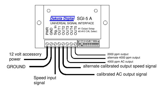


|
Help spread the ROCKCRAWLER world!
|