With the supercharged L67 3800 and it's "cabin" facing intake, lifting the motor up for removal would require pulling the throttle body...to make that easier; I've removed the tube and will get interlocking tube clamps to reattach/remove as needed. Fortunately, the cage structure is so solid, the first sawzall cut just barely jammed the blade.
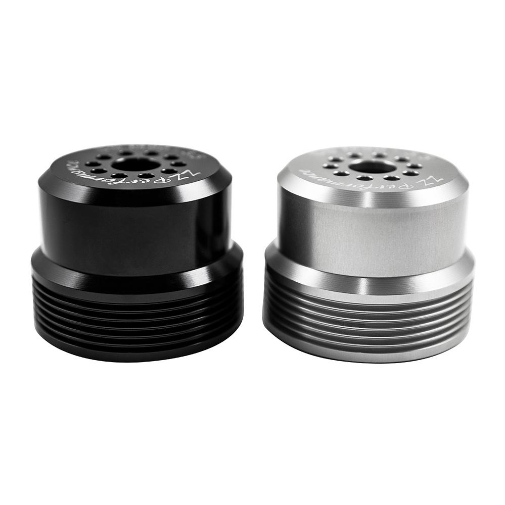
Look closely and you can see the 1" offset ZZP pulley....this allows for a single serpentine belt. I kept the stock diameter.
ZZPerformance's 1" Offset Pulleys work with our hub system and includes a pulley of your choice, 5 stainless socket cap button screws, and one barbed retainer. Modular Pulley Systems are a must for modifying your car in the future.
Fun with transfer cases?!!? Parts swapping between two Dana 300s...keeping my 32 spline front and rear outputs, swapping out the 4:1 Lomax gears for stockers, and re-sealing as needed.
The transmission cross member is ready to be welded.
And for the bling, an aluminum intake tube
I am being as patient as I can be with Behemoth for their billet D300 case, but 3 months beyond the delivery promise has me about done. For the 10th time, it's shipping tomorrow.
I can't believe all the T case work that you have been doing. Sucks for Behemoth as well, they better get s shipping confirmation today... been long enough. And I think that mount is simple and effective.
First off, WE HAVE PORTALS!! Still waiting for Jesse's laser cut link tab kit, but hoping to get these mocked up shortly.
Seat mounts: Stole some of the tabs that @Lil Rich had to get an initial mockup for my seats and start the interior tube work for the dash and such. Still working thru some unique oddities with the 3800SC motor and it's rear-facing intake position, but believe we have a plan.
I modified Jesse's original brake pedal bracketry to allow for a heel pocket. The original design placed the horizontal bracket flush with the top of the rocker tube. Positioning it on the bottom edge of the tube allows for a ~1-1/2" deep heel pocket, and that's helpful with my 6'3" frame.
Also started getting ideas for placement of the M40 shifter from Sand Hollow Offroad. Between that, transfer case levers and rear cutting brake levers (plus switches for rear steer and the rear locker) it'll be a trick to position everything...both for space and ergonomics. The shifter needs to be located to easily make quick moves from 1st to reverse, and the cutters needs to be located so the pull starts almost at arms reach. I'm guessing the rear steer and rear locker switches will be located either on the front face of the shifter, or just off to the passenger side. Decisions decisions....
I'd initially intended to mount my Optima ahead of the motor and behind the winch place on the drivers side (short V6 means plenty of space)....but @Lil Rich noted that the battery could reside below the drivers feet (and in my case, behind the heel pocket area). Definitely another good option, and it helps keep weight low.
BTW: I'll be updating the first post in the next day/two with part numbers for everything....partly for those looking for ideas, but also for my own aging memory
I'm so in love with these builds. It's awesome building them side by side so you can work out some quirks as you learn from one to the other (and borrow tabs and such).
More with dash design... Top panel will be a trapezoid that's 19" wide at the A pillar and tapers to 10". The vertical panel will be 10" wide and around 14" tall (meeting at the top of the trans)
May adjust and pull it back another inch closer to the firewall... Decisions decisions...
(bungee aided design at its finest!)
Dropped my cardboard cutout in place, plus the Rugged dualband and a too-large triple gauge cluster... Room for a battery disconnect ahead of the gauge too. And, there should be room to turndown the intake hose and have it exit into the passenger footwell for the air cleaner, and allow more space/options for switches and such. More hhmmmm
You are at one of the hardest stages. Nothing is set in stone so everything is a variable. Once you start locking in some decisions it will get a little easier.
Steering is mocked in...orbital sits just above/behind the winch plate.
The view from the drivers position....the u-joint is hidden by the steering wheel perfectly. Tip your head to the drivers side slightly and you can see the front "bumper".
Two steering joints to snake everything inside the chassis and maximize visibility. Cut the "ears" off this for the steering shaft bushing/support
Laser Innovations 03-111 Weld-On 3/4" Steering Shaft Support Bracket With Bronze Bushings for offroad racing in the King of the Hammers, New Zealand Taupo 1000, Dakar Rally, Tatts Finke Desert Race, Score International Baja 500 or Baja 1000, NORRA 500, NORRA Mexican 1000, Mint 400, Vegas to...
Is the multi-joint mechanical steering designed to place the orbital far from the driver, or to place it closer to the pump and front steering ram? There is a lot of new hydraulic thinking that I have not kept up with.
So, I decided the seat angle on the PRP's was a bit to relaxed, and that a slightly straighter seatback would be more suited to my normal driving position, as well as allow for better thigh support in the car. @Lil Rich suggested putting them in the press and squishing them....carefully....and, it worked!!
The crossbar of the 20T press is removed, and the angle iron support bar just above the floor was double padded with a weld blanket and a retired airplane blanket....the front mounting seat points were carefully aligned with that bar, the V between the feet and the bar at the front of the cushion. A 2x2x10"ish piece of .250 angle iron, with a couple short angles welded to the V to provide a flat spot for the press, was placed on the top of the seat....again, a retired airplane blanket and a canvas bag for cushion and protection.
Three measurements were taken to be SURE I could duplicate the process equally on both seats. 1> measure from the sub-harness slot to the top of the seat... 2> measure from the concrete floor to the top of the seat... and 3> measure the distance that the hydraulic jack started at when pressure began and MOST IMPORTANT...the distance it was stopped at (to ensure both were squeezed equally) That measurement was taken between the spring and the jack.
In my case, the compressed/final distance was 13"....started at 11.5". 1.5" of ram pressure applied to "squeeze" the seats tighter. And YES, they turned out perfectly!!
Since the rear link tabs were all welded in, there was no reason to stall on getting the rear axle in position, the spindles installed, and getting the tires/wheels on.
Tonight, shifter mockup....to put Reverse a comfortable distance away, the forward edge of the shifter is recessed into the dash. 1/8" plate with nutserts to hold the front edge, new bracket to mount the rear pending. (Or...just leave the wood....ha) Will get a seat mounted tmrw and test fit.
This site uses cookies to help personalise content, tailor your experience and to keep you logged in if you register.
By continuing to use this site, you are consenting to our use of cookies.